Overview
Note: this document describes the scene description format for pbrt-v2, the version of the system that accompanies the second edition of the book. See the pbrt-v3 scene description documentation for the version of pbrt corresponding to the third edition.
This document is a reference to the file format used in the pbrt; it serves as a comprehensive reference.
The scene description files used by pbrt are plain text files. The file format was designed so that it would be both easy to parse and easy for applications to generate from their own internal representations of scenes.
A pbrt scene file consists of a series of statements; different statements specify the geometry and light sources in the scene and set overall rendering parameters (such as which light transport algorithm to use or the image resolution). Each statement in these files corresponds directly to a pbrt API function from Appendix B in the Physically Based Rendering book. For example, when the WorldBegin statement appears in the input, the pbrtWorldBegin() function is called. To best understand this document, you should already be familiar with the concepts introduced in Appendix B, though we will try to re-introduce some key concepts from that appendix here.
Example of a pbrt file
Here is a short example of a pbrt input file: Between the start of the file and the WorldBegin statement, overall options for rendering the scene are specified, including the camera type and position, the sampler definition, and information about the image to be generated. After WorldBegin, the lights, geometry, and scattering volumes (if any) in the scene are defined, up until the WorldEnd statement, which causes the image to be rendered.
LookAt 0 10 100   0 -1 0 0 1 0
Camera "perspective" "float fov" [30]
PixelFilter "mitchell" "float xwidth" [2] "float ywidth" [2]
Sampler "bestcandidate"
Film "image" "string filename" ["simple.exr"]
     "integer xresolution" [200] "integer yresolution" [200]

WorldBegin
AttributeBegin
  CoordSysTransform "camera"
  LightSource "distant"
              "point from" [0 0 0] "point to"   [0 0 1]
              "rgb L"    [3 3 3]
AttributeEnd

AttributeBegin
  Rotate 135 1 0 0
  Texture "checks" "spectrum" "checkerboard"
          "float uscale" [4] "float vscale" [4]
          "rgb tex1" [1 0 0] "rgb tex2" [0 0 1]
  Material "matte"
           "texture Kd" "checks"
  Shape "disk" "float radius" [20] "float height" [-1]
AttributeEnd
WorldEnd
When rendered with pbrt, this image is
generated for this scene: 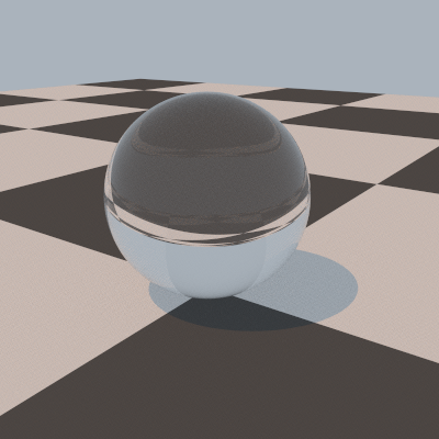
General structure of a pbrt input file
A scene description file starts with a series of directives that describe the camera, film, and sampling and light transport algorithms to use in rendering the scene. These are followed by the WorldBegin directive; after WorldBegin, the world definition block starts, and it is no longer legal to specify different definitions of any of the objects defined in the initial section of the file. However, lights, materials, textures, shapes, and volumetric scattering regions can be defined inside the world block (and can only be defined inside the world block). The world block ends with the WorldEnd directive; when this is encountered, the Renderer defined takes control and does the required rendering computation.
The hash character # denotes that the rest of the line is a comment and should be ignored by the parser.
The following section, Scene-wide rendering options, documents the directives that are valid outside of the world definition block. The subsequent section, Describing the scene, documents the directives for defining the shapes, materials, lights, etc., that define the scene.
Some of the statements in the input file, such as WorldBegin, AttributeEnd, and so on, have no additional arguments. Others, such as those related to specifying transformations, such as Rotate and LookAt, take a predetermined number of arguments of predetermined type. (For example, Translate is followed by three floating-point values that give the x, y, and z components of the translation vector. The remainder of the statements take a variable number of arguments and are of the form
identifier "type" parameter-list
For example, the Shape identifier describes a shape to be added to the scene, where the type of shape to create is given by a string (e.g. "sphere") and is followed a list of shape-specific parameters that define the shape. For example,
Shape "sphere" "float radius" [5]
defines a sphere of radius 5. (See Shapes for documentation of the parmeters taken by the various shapes implemented in pbrt.)
Here, the "type" string gives the name of the particular shape, etc., implementation to use, and parameter-list gives the parameters to pass to the plug-in. With this design, the parser doesn't need to know anything about the semantics of the parameters; it just needs to know how to parse parameter lists and how to initialize a ParamSet from them (The ParamSet class is described on page 1047 of the Physically Based Rendering book).
Almost all directives in a pbrt input file have a direct correspondence with a function in the pbrt API, defined in the files core/api.h and core/api.cpp. The only input file directive that does not directly correspond to a function in the API is the Include statement, which allows other input files to be parsed. Include behaves similarly to the #include directive in C++, except that only the directory that the currently-being-processed input file is searched for matching filenames. Of course, a complete pathname or a path relative to the current directory can be specified if appropriate.
Include "geometry/car.pbrt"
Parameter Lists
Variable-length lists of named parameters and their values are the key meeting ground between the parsing system and the objects that are created to represent the scene. Each of these lists holds an arbitrary number of name/value pairs, with the name in quotation marks and the value or values in square brackets:
"type name" [ value or values ]
For example,
"float fov" [30]
specifies a parameter "fov" that is a single floating-point value, with value 30. Or,
"float cropwindow" [0 .5 0 .25]
specifies that "cropwindow" is a floating-point array with the given four values. Notice that values are enclosed in square brackets. Single values (such as the "30" in the "fov" example above) may be provided with or without square brackets enclosing them, though arrays of values always must be enclosed in square brackets.
The type of each parameter must always be given along with its name; pbrt has no built-in knowledge of any parameter names. This simplifies the parsing system, although it does create a small burden for the creator of the input file.
pbrt supports seven basic parameter types: integer, float, point, vector, normal, spectrum, bool, and string. The point, vector, and normal types all take three floating-point values to specify each value. string parameters must be inside quotation marks, and bool parameters are set with the strings "true" and "false", quotation marks included.
"string filename" "foo.exr"
"point origin" [ 0 1 2 ]
"normal N" [ 0 1 0  0 0 1 ] # array of 2 normal values
"bool renderquickly" "true"
pbrt provides a number of ways of specifying spectral values in scene description files. RGB values are commonly used, though see Section 5.2.2 on page 273 of the second edition of "Physically Based Rendering" for discussion of the shortcomings of this representation. RGB color values can be specified with the rgb type. (color is also supported as a synonym for this):
"rgb Kd" [ .2 .5 .3 ]
specifies the RGB color with red equal to 0.2 and so forth. The FromRGB() method of the Spectrum implementation being used is used to convert the given RGB colors to the current spectral representation.
Alternatively, XYZ colors can be used to specify a spectrum:
"xyz Kd" [ .4 .6 .7 ]
General sampled SPDs are specified with a series of (wavelength, value) pairs, where wavelengths are specified in nm. These SPDs are resampled to the current spectral representation with its FromSampled() method. For example,
"spectrum Kd" [ 300 .3 400 .6 410 .65 415 .8 500 .2 600 .1 ]
specifies a piecewise-linar SPD with a value of 0.3 at 300nm, 0.6 and 400nm, and so forth. Since complex sampled SPDs may have many values, they can also be provided through a separate file:
"spectrum Kd" "filename"
Where the filename specifies the path to a plain text file with pairs of floating-point (wavelength, value) as above. The parser for these files allows uses # to denote a comment that goes to the end of the current line. See the directory scenes/spds in the pbrt distribution for examples.
Finally, SPDs of blackbody emitters can be specified with two floating-point values, one giving the blackbody temperature in Kelvin, and the second giving a scale factor. See the Wikipedia article on blackbody emitters for more information and the formula used to compute the SPD from the blackbody temperature:
"blackbody L" [ 6500 1 ] # daylight, approximately
Transformations
A series of directives modify the current transformation marix (CTM). (See Section B.2.2 on page 1053 for more information about how the CTM is maintined during scene description.) When the scene's camera is specified with a Camera directive, the CTM defines the world to camera transformation; when a light or shape is created, the CTM specifies the transformation from object space to world space.
When parsing begins, the CTM is the identity transformation; furthermore, it is is reset to the identity when the WorldBegin directive is encountered. The following directives change the CTM; they are shown with the corresponding pbrt API call:
| Input File Syntax | API Call |
|---|---|
| Identity | pbrtIdentity() |
| Translate x y z | pbrtTranslate() |
| Scale x y z | pbrtScale() |
| Rotate angle x y z | pbrtRotate() |
| LookAt ex ey ez lx ly lz ux uy uz | pbrtLookAt() |
| CoordinateSystem "name" | pbrtCoordinateSystem() |
| CoordSysTransform "name" | pbrtCoordSysTransform() |
| Transform m00 ... m33 | pbrtTransform() |
| ConcatTransform m00 .. m33 | pbrtConcatTransform() |
For example, Translate takes three floating-point values, x, y, and z, and the corresponding values are passed to the pbrtTranslate() API call, which in turn modifies the CTM by setting it to the product of the CTM with the matrix representing the given translation.
pbrt supports animated transformations by allowing two transformation matrices to be specified at different times. The TransformTimes directive, which must be outside of the world definition block, defines these two times with floating-point vaues:
TransformTimes start end
Then, the ActiveTransform directive indicates whether subsequent directives that modify the CTM should apply to the transformation at the starting time, the transformation at the ending time, or both. The default is that both matrices should be updated:
Translate 1 0 0  # applies to both, by default
ActiveTransform StartTime
Rotate 90 1 0 0
ActiveTransform EndTime
Rotate 120 0 1 0
ActiveTransform All
Scene-wide rendering options
This section describes rendering options that must be specified before the WorldBegin statement.
Cameras
The Camera directive specifies the camera used for viewing the scene. (The camera is used when pbrt is used to render an actual image. However, some of pbrt's Renderer implementations compute other quantities—for example, AggregateTest tests ray tracing acceleration structures and CreateRadianceProbes computes spherical harmonic radiance probes at a grid of locations—neither one of these uses the camera. See the section on Renderers for more discussion.)
The default camera is a PerspectiveCamera with a 90 degree field of view:
Camera "perspective" "float fov" [90]
When the Camera directive is encountered in an input file, the current transformation matrix is used to initialize the world-to-camera transformation.
pbrt provides three camera implementations:
| Name | Implementation Class |
|---|---|
| "environment" | EnvironmentCamera |
| "orthographic" | OrthoCamera |
| "perspective" | PerspectiveCamera |
A number of parameters are common to all cameras in pbrt:
| Type | Name | Default Value | Description |
|---|---|---|---|
| float | shutteropen | 0 | The time at which the virtual camera shutter opens. |
| float | shutterclose | 1 | The time at which the virtual camera shutter closes. |
| float | frameaspectratio | (see description) | The aspect ratio of the film. By default, this is computed from the x and y resolutions of the film, but it can be overridden if desired. |
| float[4] | screenwindow | (see description) | The bounds of the film plane in screen space. By default, this is [-1,1] along the shorter image axis and is set proportionally along the longer axis. |
The EnvironmentCamera takes no additional parameters beyond these. PerspectiveCamera and OrthoCamera support images rendered with depth of field. They both use the following two parmaeters to set the lens focus, etc.
| Type | Name | Default Value | Description |
|---|---|---|---|
| float | lensradius | 0 | The radius of the lens. Used to render scenes with depth of field and focus effects. The default value yields a pinhole camera. |
| float | focaldistance | 10^30 | The focal distance of the lens. If "lensradius" is zero, this has no effect. Otherwise, it specifies the distance from the camera origin to the focal plane. |
Finally, the perspective camera has two (semi-redundant) parameters for setting the camera's field of view.
| Type | Name | Default Value | Description |
|---|---|---|---|
| float | fov | 90 | Specifies the field of view for the perspective camera. This is the spread angle of the viewing frustum along the narrower of the image's width and height. |
| float | halffov | n/a | For convenience to some programs that export from modeling systems, the camera's field of view can also be specified via the half-angle between the view direction and the edge of the viewing frustum. If this parameter isn't provided, then fov is used to set the field of view instead. |
Samplers
The Sampler generates samples for the image, time, lens, and Monte Carlo integration. A number of implementations are provided; the default is "lowdiscrepancy"—the LDSampler. Note that the sampler is only used if SamplerRenderer is the Renderer being used to render the scene; other renderers have their own sample generation mechanisms internally and/or don't need samples in this manner (e.g. AggregateTest).
| Name | Implementation Class |
|---|---|
| "adaptive" | AdaptiveSampler |
| "bestcandidate" | BestCandidateSampler |
| "halton" | HaltonSampler |
| "lowdiscrepancy" | LDSampler |
| "random" | RandomSampler |
| "stratified" | StratifiedSampler |
The HaltonSampler and StratifiedSampler are not as effective as the LDSampler, AdaptiveSampler, or BestCandidateSampler; the sample points they generate aren't as good and thus more samples will generally be required to get a similar result. The RandomSampler generates particularly ineffective sampling patterns. It is really only useful for comparison against more sophisticated approaches and shouldn't otherwise be used.
The AdaptiveSampler takes a minimum number of samples in each pixel and then performs a test to see if, according to some metric, they vary excessively. If so, it takes a higher number of samples. The underlying sample generation algorithms are based on the low-discrepancy patterns used by the LDSampler.
| Type | Name | Default Value | Description |
|---|---|---|---|
| integer | minsamples | 4 | This is the initial number of samples taken inside each pixel area. |
| integer | maxsamples | 32 | If the variation test indicates that this is a complex pixel area, then this number of samples is taken. |
| string | method | contrast | This parameter sets which test to use to see if a pixel is varying excessively. The two supported values are "contrast", which indicates that the color contrast between the sample values should be compared toa threshold, and "shapeid", which indicates that if different shapes are visible in the pixel area, additional samples should be taken. |
The "bestcandidate", "lowdiscrepancy", "halton", and "random" samplers all take a single parameter, "pixelsamples", which sets the number of samples to take in each pixel area.
| Type | Name | Default Value | Description |
|---|---|---|---|
| integer | pixelsamples | 4 | The number of samples to take, per pixel. Note that the number of samples is taken per pixel on average; depending on the actual sampling algorithm being used, individual pixel areas may have slightly more or slightly fewer. |
The "stratified" sampler has three parameters that control its behavior.
| Type | Name | Default Value | Description |
|---|---|---|---|
| bool | jitter | "true" | Whether or not the generated samples should be jittered inside each stratum; this is generally only worth setting to "false" for comparisons between jittered and uniform sampling—uniform sampling will almost always give a worse result. |
| integer | xsamples | 2 | The number of samples per pixel to take in the x direction. |
| integer | ysamples | 2 | The number of samples per pixel to take in the y direction. In general, "xsamples" and "ysamples" should be set to the same value for best results. |
Film
The Film directive specifies the characteristics of the image being generated by the renderer. Note that only the SamplerRenderer and the MetropolisRenderer use the film; the other renderers don't generate an image per se and thus ignore the film definition.
The only Film implementation currently available in pbrt is ImageFilm which is specified as "image" in input files. For example:
Film "image" "string filename" ["out.exr"]
             "float cropwindow" [ .2 .5 .3 .8 ]
The "image" film takes a handful of parameters:
| Type | Name | Default Value | Description |
|---|---|---|---|
| integer | xresolution | 640 | The number of pixels in the x direction. |
| integer | yresolution | 480 | The number of pixels in the y direction. |
| float[4] | cropwindow | [ 0 1 0 1 ] | The subregion of the image to render. The four values specified should be fractions in the range [0,1], and they represent x_min, x_max, y_min, and y_max, respectively. These values are in normalized device coordinates, with (0,0) in the upper-left corner of the image. |
| string | filename | "pbrt.exr" | The output filename. |
The ImageFilm uses the suffix of the given output filename to determine the image file format to use. All builds of pbrt support PFM and TGA format images; those configured to use the OpenEXR libraries support EXR as well.
Filters
The implementation of ImageFilm uses an instance of the abstract Filter class to filter sample values to compute final pixel values. (Thus, as only the SamplerRenderer and the MetropolisRenderer use ImageFilm, the filter setting is only relevant when one of those renderers is being used.
pbrt provides a number of filter implementations, listed below. The default is "box"; while the box filter has a number of known shortcomings, it is the most effective filter when the low-discrepancy sampler is being used (recall the illustration in Figure 7.37 on page 392 of Physically Based Rendering).
| Name | Implementation Class |
|---|---|
| "box" | BoxFilter |
| "gaussian" | GaussianFilter |
| "mitchell" | MitchellFilter |
| "sinc" | LanczosSincFilter |
| "triangle" | TriangleFilter |
All filter implementations take two parameters that set the filter width in each direction. Typically, these two parameters will have the same value.
| Type | Name | Default Value | Description |
|---|---|---|---|
| float | xwidth | 2 (0.5 for box, 4 for sinc) | The width of the filter in the x direction. |
| float | ywidth | 2 (0.5 for box, 4 for sinc) | The width of the filter in the y direction. |
The "gaussian" filter takes an additional parameter that adjusts the rate of Gaussian falloff; see page 397 for more information.
| Type | Name | Default Value | Description |
|---|---|---|---|
| float | alpha | 2 | alpha controls the falloff rate of the Gaussian filter. Smaller values give a blurrier image. |
Two parameters set the shape of the "mitchell" filter; see the equation on the top of page 400.
| Type | Name | Default Value | Description |
|---|---|---|---|
| float | B | 1/3 | |
| float | C | 1/3 | These parameters control the shape of the Mitchell filter. The best results are generally obtained when B+2C=1. |
Finally the sinc filter takes a value tau that sets the number of cycles of the sinc function.
| Type | Name | Default Value | Description |
|---|---|---|---|
| float | tau | 3 | tau controls how many cycles the sinc function passes through before it is clamped to zero by the windowing function. |
Renderers
The renderer, defined with the Renderer directive, selects the rendering algorithm used to render the scene. For example:
Renderer "metropolis" "integer samplesperpixel" [4096]
pbrt sometimes has a somewhat broad uage for "render the scene" in that some of the Renderer implementations don't actually generate images.
The default renderer is "sampler", corresponding to the SamplerRenderer. The following Renderer implementations are currently available in pbrt.
| Name | Implementation Class |
|---|---|
| "aggregatetest" | AggregateTest |
| "createprobes" | CreateRadianceProbes |
| "metropolis" | MetropolisRenderer |
| "sampler" | SamplerRenderer |
| "surfacepoints" | SurfacePointsRenderer |
The "aggregatetest" renderer is one that doesn't create an image. Instead, it traces a number of random rays using the current acceleration structure (see Accelerators for information about how the accelerators are selected) and checks the results to the result from an exhaustive intersection of each ray with all of the triangles in the scene. This renderer can thus be used to find bugs in the implementation of accelerators; see Section 4.6 on page 245 for more information.
| Type | Name | Default Value | Description |
|---|---|---|---|
| integer | niters | 100000 | Number of random rays to generate to use for testing the aggregate. |
The "createprobes" renderer computes a series of spherical harmonic radiance probes; see Section 17.3 on page 956 for more information. This renderer uses whichever surface and volume integrators are specified in the input file; see the following sections, Surface Integrators and Volume Integrators for more information.)
| Type | Name | Default Value | Description |
|---|---|---|---|
| float[6] | bounds | (none) | Bounding box (x0, y0, z0) - (x1, y1, z2) within which to compute radiance probes. If this is not specified, then the entire scene bounding box is used. |
| bool | directlighting | true | Determines whether direct illumination should be included in the computed incident radiance function. Some applications only include indirect radiance in the probes and use conventional techniques to render direct illumination. |
| string | filename | "probes.out" | Filename of file in which to store SH coefficients of radiance probes. |
| bool | indirectlighting | true | In a similar fashion, this parameter determines whether indirect illumination should be included in the radiance probes. |
| integer | lmax | 4 | Number of spherical harmonic bands to use to represent the incident radiance function. |
| integer | indirectsamples | 512 | Number of Monte Carlo samples to use to compute indirect illumination at each probe point. |
| float | samplespacing | 1 | Desired, in world space distance, between the radiance probes. The resolution of the grid of sample points is set so that the distance between samples is no greater than this distance along any of the x, y, or z axes. |
| float | time | Time at which to sample the incident radiance to compute the probes. |
The "metropolis" renderer implements the Metropolis light transport algorithm; it is defined in Section 15.7 of the Physically Based Rendering book.
| Type | Name | Default Value | Description |
|---|---|---|---|
| float | largestepprobability | 0.25 | Probability of the mutation strategy proposing a mutation where all of the sample values are replaced with completely new samples (versus a "small step" where the current sample values are only perturbed). In general, this value should be in the range 0.05 and 0.5. For scenes with particularly difficult-to-sample light transport paths, lower values may be more effective. |
| integer | samplesperpixel | 100 | Average number of samples per pixel to take. (In other words, the total number of samples taken is the product of the image resolution and this parameter's value.) |
| integer | bootstrapsamples | 100000 | Number of Monte Carlo samples to take to compute the estimate of the overall image brightness. For scenes with difficut-to-sample light transport paths, increasing this value may give better results, particularly when rendering animations. (Otherwise, if there is too much variance in this estimate, some frames may be too bright and others too dark.) |
| integer | directsamples | 4 | If direct lighting is being performed separately from Metropolis sampling, this gives the number of samples per pixel to take to compute the direct lighting component. |
| bool | dodirectseparately | true | Whether or not direct lighting should be included Metropolis sampling. For scenes where the direct lighting is handled well with conventional techniques, then it will often be more efficient to handle it separately, allowing the use of variance reduction approaches like low-discrepancy sampling patterns. For scenes with difficult-to-sample direct lighting, it's better to use Metropolis for this as well. |
| integer | maxconsecutiverejects | 512 | Maximum number of repeated rejections of a proposed sample mutation. If this many rejections occur in a row, the next sample is unconditionally accepted. This can prevent the system from getting stuck in a subset of the overall path space. |
| integer | maxdepth | 7 | Maximum number of light scattering bounces to follow when tracing paths through the scene. |
| bool | bidirectional | true | Indicates whether bidirectional path tracing should be used (versus standard path tracing.) It's almost always worthwhile to use bidirectional path tracing. |
The "sampler" renderer uses the defined Sampler to provide samples that it in turn uses to generate camera rays and then call the SurfaceIntegrator and VolumeIntegrator to compute the radiance along those rays. This is the default renderer in the system. In general, parameters that control its operation are set indirectly via parameters to the Sampler, SurfaceIntegrator, and VolumeIntegrator.
| Type | Name | Default Value | Description |
|---|---|---|---|
| bool | visualizeobjectids | "false" | This renderer can optionally ignore the surface and volume integrators and randomly shade objects based on their shape and primitive id values. This can be useful to visualize the tessellation of complex objects and search for problems in geometric models. |
The "surfacepoints" renderer computes a set of sample points on the surfaces of objects in the scene that have BSSRDF materials (i.e. that exhibit subsurface scattering). These sample points are distributed on the surface according to a Poisson sphere criterion so that no two of them are too close together. Because the generation of these points can be computationally complex, it's often worth doing it in a preprocess; the DipoleSubsurfaceIntegrator can then read these files of sample points and use them at rendering time.
| Type | Name | Default Value | Description |
|---|---|---|---|
| float | minsampledistance | 0.25 | Minimum distance allowed between any pair of sample points. |
| string | filename | (none) | Filename in which to save the generated points. An text file format is used; a comment at the start of the file describes its structure. |
Surface Integrators
The surface integrator implements the light transport algorithm that computes reflected radiance from surfaces in the scene. Recall that surface integrators are only used by the SamplerRenderer and CreateRadianceProbes renderer; if another renderer is specified, then the surface integrator is ignored. The default surface integrator is the DirectLightingIntegrator:
SurfaceIntegrator "directlighting" "integer maxdepth" [5]
    "string strategy" "all"
A number of other surface integrators are available in the system.
| Name | Implementation Class |
|---|---|
| "ambientocclusion" | AmbientOcclusionIntegrator |
| "diffuseprt" | DiffusePRTIntegrator |
| "dipolesubsurface" | DipoleSubsurfaceIntegrator |
| "directlighting | DirectLightingIntegrator |
| "glossyprt" | GlossyPRTIntegrator |
| "igi" | IGIIntegrator |
| "irradiancecache" | IrradianceCacheIntegrator |
| "path" | PathIntegrator |
| "photonmap" | PhotonIntegrator |
| "useprobes" | UseRadianceProbes |
| "whitted" | WhittedIntegrator |
A greyscale ambient occlusion image is computed by the "ambientocclusion" integrator; it takes a number of samples over the hemisphere of each visible point and computes the fraction of them that are unoccluded.
| Type | Name | Default Value | Description |
|---|---|---|---|
| integer | nsamples | 2048 | Number of samples to take in computing the ambient occlusion value. Lower values will be faster, but may lead to noisy images. |
| float | maxdist | (infinite) | Distance beyond which to ignore any intersections for the ambient occlusion computation. Often, considering only nearby occluders gives good results and can be much more efficient, as the rays to be traced are shorter. |
The "diffuseprt" integrator implements the diffuse precomputed radiance transfer algorithm implemented in Section 17.4 of Physically Based Rendering. At each point, it projects the transfer function (Equation 17.20) into the SH basis and uses the efficient dual-product integral approach to compute the reflected light due to incident illumination. (Recall that in practice, one would generally want to precompute the projection of the transfer function and store it and then do the reflected light computation in real-time.)
| Type | Name | Default Value | Description |
|---|---|---|---|
| integer | lmax | 4 | Maximum spherical harmonic band l to use; the total number of SH coefficients used at each point will be (lmax+1)*(lmax+1). |
| integer | nsamples | 4096 | Number of Monte Carlo samples to use when computing the projection of the transfer function T (Equation 17.20) into the spherical harmonics basis. |
The "dipolesubsurface" integrator implements the subsurface scattering rendering algorithm described in Section 16.5. It is otherwise similar to the direct lighting integrator, in that it follows specularly reflected and transmitted rays and uses standard algorithms to compute direct lighting.
| Type | Name | Default Value | Description |
|---|---|---|---|
| integer | maxdepth | 5 | The maximum recursion depth for specular reflection and transmission. |
| float | maxerror | 0.05 | Maximum value of the error term used to determine whether to traverse deeper into the irradiance sample octree or to use the current node for illumination. (This is the maxError value in the second code fragment from the top of page 911.) |
| float | minsampledistance | 0.25 | Minimum distance between the point samples generated on translucent objects at which to compute the incident irradiance. In general, this value should be around half of the mean free path of light inside the scattering medium. The value of this parameter is ignored if the "pointsfile" parameter is provided. |
| string | pointsfile | (none) | File from which to read precomputed sample points (as generated by the SurfacePointsRenderer, for example.) If a file is provided, the points to be used will be read from the file. Otherwise, the point generation step will be performed using the provided "minsampledistance" before rendering. |
There are two parameters for the "directlighting" integrator.
| Type | Name | Default Value | Description |
|---|---|---|---|
| integer | maxdepth | 5 | The maximum recursion depth. |
| string | strategy | "all" | The strategy to use for sampling direct lighting. Valid options are "all", which samples all the lights uniformly and averages their contributions, and "one", which chooses a single light uniformly at random. |
The "glossyprt" integrator implements the glossy precomputed radiance transfer algorithm described in Section 17.5 of Physically Based Rendering. As with the "diffuseprt" integrator, it both computes the SH representation of scattering at each point and then computes the effect of this scattering with the light in the scene. In general, one would precompute the scattering properties and then compute the scattering in a real-time renderer.
Furthermore, note that this integrator ignores the properties of the materials bound to objects in the scene but instead uses a simple parameterized material model for all scene objects. The reasons for this, and alternative approaches are discussed at the top of page 980.
| Type | Name | Default Value | Description |
|---|---|---|---|
| integer | lmax | 4 | Maximum SH band number l to use. Given a particular value of lmax, (lmax+1)*(lmax+1) SH coefficients will be used. |
| integer | nsamples | 4096 | Number of Monte Carlo samples to use in the various computations projecting quantities into SH. |
| spectrum | Kd | 0.5 | Diffuse reflectance spectrum of surfaces. |
| spectrum | Ks | 0.25 | Glossy reflectance of surfaces. |
| float | roughness | 0.1 | Surface roughness, for use with the Blinn microfacet distributions. |
The "instant global illumination" algorithm is implemented by the "igi" integrator.
| Type | Name | Default Value | Description |
|---|---|---|---|
| integer | maxdepth | 5 | The maximum recursion depth for specular reflection and transmission. |
| integer | nlights | 64 | The number of virtual light paths to follow for each of the light sets. The more paths followed, the better the result in general, though the longer rendering takes. |
| integer | nsets | 4 | The number of independent virtual light sets to compute. In general, this number should be equal to the number of pixel samples taken by the sampler; this should ensure that in each pixel area, each of the light sets is used exactly one time. If this number is larger than the number of pixel samples, the image may be noisy, as different pixels will use different virtual lights. |
| float | rrthreshold | 0.0001 | Russian roulette threshold for terminating shadow rays that connect the point being shaded to a virtual light source. |
| float | glimit | 10 | Maximum allowed value of the geometric coupling term G; see Equations 15.11 through 15.12 on pages 782-783. If images have unexpected bright regions, reducing this value should cause them to disappear. |
| integer | gathersamples | 16 | Number of "final gather" samples to take at points where the G limit was applied. |
The irradiance caching integrator is used when the "irradiancecache" SurfaceIntegrator is specified.
| Type | Name | Default Value | Description |
|---|---|---|---|
| float | minweight | 0.5 | Minimum weight for the interpolated irradiance samples. If the sum of interpolated sample weights is less than this value, a new sample is computed. |
| float | minpixelspacing | 2.5 | Minimum distance, in pixels, between irradiance samples. No samples nearer this distance will be generated. |
| float | maxpixelspacing | 15 | Maximum distance, in pixels, between irradiance samples. Even if the other error terms indicate that a sample can be used at a point being shaded, if it is more than this many pixels away on the image plane, it is ignored. |
| float | maxangledifference | 10 | Maximum allowed difference in the angle between the surface normal at an irradiance lookup point and the surface normal of an irradiance sample. |
| integer | maxspeculardepth | 5 | Maximum recursion depth for tracing specular reflection and refraction rays. |
| integer | maxindirectdepth | 3 | Maximum recursion depth for tracing paths to compute irradiance estimates. |
| integer | nsamples | 4096 | How many rays are used to estimate the irradiance value at a point. |
The "path" integrator takes just a single parameter.
| Type | Name | Default Value | Description |
|---|---|---|---|
| integer | maxdepth | 5 | The maximum length of a path. |
Photon mapping is implemented by the "photonmap" integrator.
| Type | Name | Default Value | Description |
|---|---|---|---|
| integer | causticphotons | 20,000 | The number of photons required to build the caustic photon map. The more caustic photons traced, the more accurately caustics will be represented in the scene, though the more memory will be required to store them. |
| integer | indirectphotons | 100,000 | The number of photons required to build the indirect illumination map. As with caustic photons, increasing the number of photons improves the result at the cost of more memory. |
| integer | nused | 50 | The number of photons to use in density estimation. |
| integer | maxspeculardepth | 5 | The maximum number of levels of specular reflection and refraction. |
| integer | maxphotondepth | 5 | The maximum number of levels of scattering to follow when tracing photon paths from light sources. |
| float | maxdist | 0.1 | The maximum distance between a point being shaded and a photon that can contribute to that point. |
| bool | finalgather | true | If true, do a final gather when estimating the indirect illumination. Otherwise, just use the photon map at the hit point. (In general, final gathering gives substantially better results, but is much more computationally intensive.) |
| integer | finalgathersamples | 32 | Number of samples to use when performing the final gather. In general, a few thousand or so final gather samples are needed in each pixel area to give good results. However, it's the product of the number of pixel samples and the number of final gather samples that matters; for 32 or 64 pixel samples at each pixel, this default generlaly works well. |
| float | gatherangle | 10 | The photons around the point being shaded are used to construct an importance sampling distribution for final gathering by computing small cones around the incident direction of each one. (The notion being that these directions indicate the important directions for incident indirect illumination at the point.) This parameter sets the spread angle of these cones. Too narrow an angle may miss important indirect illumination directions, while too wide an angle may reduce the effectiveness of this small optimization. |
The "useprobes" integrator uses a set of radiance probes encoded in spherical harmonics, such as those computed by the CreateRadianceProbes renderer. At each point being shaded, it computes the diffuse reflectance and then uses the SH convolution formula to compute the outgoing scattered radiance due to the incident illumination in the scene.
| Type | Name | Default Value | Description |
|---|---|---|---|
| string | filename | "probes.out" |
The "whitted" integrator takes a single parameter that sets the maximum ray tree depth. In general, the "directlighting" integrator should be used in preference to the "whitted" integrator, as it uses better sampling algorithms for direct lighting from area light sources. (The "whitted" integrator is simplified in this respect for better clarity of presentation of the basic ray tracing algorithm.)
| Type | Name | Default Value | Description |
|---|---|---|---|
| integer | maxdepth | 5 | The maximum recursion depth. |
Volume Integrators
pbrt provides two volume integrators; the default is EmissionIntegrator, which only accounts for volumetric attenuation and emission. The SingleScatteringIntegrator computes the effect of single scattering and can thus render volumetric shadows, though it can be substantially more computationally intensive.
| Name | Implementation Class |
|---|---|
| "emission" | EmissionIntegrator |
| "single" | SingleScatteringIntegrator |
Both volume integrators take a single parameter, which specifies the distance in world space along the ray to go forward at each step. In general, smaller values will cause rendering to take longer, but will better resolve fine-scale details in the volume description.
| Type | Name | Default Value | Description |
|---|---|---|---|
| float | stepsize | 1 | The stepping distance along a ray when doing ray marching. |
Accelerators
The type of aggregate to use for efficiently finding ray-shape intersections is defined with the Accelerator directive:
Accelerator "kdtree" "float emptybonus" [0.1]
The default accelerator, "bvh", is generally a good choice; it is rarely worthwhile to specify a different accelerator or to need to change the accelerator's parameters to improve performance.
Three accelerator implementations are available in pbrt:
| Name | Implementation Class |
|---|---|
| "bvh" | BVHAccel |
| "grid" | GridAccel |
| "kdtree" | KdTreeAccel |
The "bvh" accelerator, the default, takes just two parameters. This accelerator is efficiently constructed when the scene description is processed, while still providing highly efficient ray-shape intersection tests.
| Type | Name | Default Value | Description |
|---|---|---|---|
| integer | maxnodeprims | 4 | Maximum number of primitives to allow in a node in the tree. Once the primitives have been split to groups of this size or smaller, a leaf node is created. |
| string | splitmethod | "sah" | Method to use to partition the primitives when building the tree. The default, "sah", denotes the surface area heuristic; the default should almost certainly be used. The other options—"middle", which splits each node at its midpoint along the split axis, or "equal", which splits the current group of primitives into two equal-sized sets—are slightly more efficient to evaluate at tree construction time, but lead to substantially lower-quality hierarchies. |
The "grid" accelerator takes only a single parameter. While this accelerator is extremely efficient to create, it is substantially lower performance than the others at ray-shape intersection time.
| Type | Name | Default Value | Description |
|---|---|---|---|
| bool | refineimmediately | false | If true, primitives are fully refined as soon as they are added to the grid. Otherwise, they are not refined until a ray enters a voxel that contains the primitive. |
Finally, the "kdtree" accelerator takes a number of parameters that control its construction. This accelerator takes substantially longer to create than "bvh" at scene definition time, but it can be marginally faster at finding ray-shape intersections. It tends to require less memory than "bvh".
See page 234 of the second edition of the book for the details of the cost function used for building kd-trees (and thus the use of some of the the various parameters below.)
| Type | Name | Default Value | Description |
|---|---|---|---|
| integer | intersectcost | 80 | The value of the cost function that estimates the expected cost of performing a ray-object intersection, for use in building the kd-tree. |
| integer | traversalcost | 1 | Estimated cost for traversing a ray through a kd-tree node. |
| float | emptybonus | 0.2 | "Bonus" factor for kd-tree nodes that represent empty space. |
| integer | maxprims | 1 | Maximum number of primitives to store in kd-tree node. (Not a hard limit; more may be stored if the kd-tree can't find splitting planes that reduce the number of primitives when refining a node.) |
| integer | maxdepth | -1 | Maximum depth of the kd-tree. If negative, the kd-tree chooses a maximum depth based on the number of primitives to be stored in it. |
Describing the scene
After the camera, film, and rendering options have been set, the WorldBegin directive marks the start of the scene definition (the "world block"). In the world block, the lights, materials, and geometric shapes that make up the scene are defined. After WorldBegin, the directives described in the Scene-wide rendering options section are all illegal; an error message will be printed if one is encountered. (Similarly, the directives documented in this section are illegal outside of the world block.) The end of the world block is denoted by the WorldEnd directive; when it is encountered, the chosen Renderer takes over and does the requested rendering computation.
Attributes
A number of directives modify the current graphics state—examples include the transformation directives (Transformations), and the directive that sets the current material. The current graphics state (including the current transformation matrix) can be saved and restored using the AttributeBegin and AttributeEnd directives:
Material "matte"
AttributeBegin
   Material "plastic"
   Shape "sphere"
AttributeEnd   # back to the "matte" material
Shape "cone"
The transformation matrix can be saved and restored independently of the graphics state using TransformBegin and TransformEnd.
Scale 2 2 2
TransformBegin
    Translate 1 0 1
    Shape "sphere"
TransformEnd   # Translate no longer applies here
In addition to the current transformation matrix and material, the reverse-orientation setting, specified by the ReverseOrientation directive, is part of the graphics state. This directive, when active, flips the surface normal of the shapes that follow it; it can be useful when specifying area light sources, which only emit light from the side their surface normal points from, and when specifying transparent materials, where the surface normal is used to determine whether rays are entering or exiting the refractive medium.
Shapes
Shapes are specified with the Shape directive; it takes the name of a shape implementation and a parameter list used to define the shape's properties:
Shape "name" parameter-list
For example,
Shape "sphere" "float radius" [0.25]
When a Shape directive is encountered, the current transformation matrix is used to set the object to world transformation for the shape.
A number of shapes are provided by pbrt; this list shows the mapping from shape names to implementation class in the system.
| Name | Implementation Class |
|---|---|
| "cone" | Cone |
| "cylinder" | Cylinder |
| "disk" | Disk |
| "hyperboloid" | Hyperboloid |
| "heightfield" | Heightfield |
| "loopsubdiv" | LoopSubdiv |
| "nurbs" | NURBS |
| "paraboloid" | Paraboloid |
| "sphere" | Sphere |
| "trianglemesh" | TriangleMesh |
The extent of the "cone" shape is defined by three parameters; note that the cone is oriented along the z axis in object space; the current transformation matrix can be used to orient it differently in the scene's world space.
| Type | Name | Default Value | Description |
|---|---|---|---|
| float | radius | 1 | The cone's radius. |
| float | height | 1 | The height of the cone along the z axis. |
| float | phimax | 360 | The maximum extent of the cone in phi (in spherical coordinates). |
Similarly, "cylinder" is oriented along the z axis as well. It takes four parameters.
| Type | Name | Default Value | Description |
|---|---|---|---|
| float | radius | 1 | The cylinder's radius. |
| float | zmin | -1 | The height of the cylinder's bottom along the z axis. |
| float | zmax | 1 | The height of the cylinder's top along the z axis. |
| float | phimax | 360 | The maximum extent of the cylinder in phi (in spherical coordinates). |
The "disk" is perpendicular to the z axis, with its center at x=0 and y=0.
| Type | Name | Default Value | Description |
|---|---|---|---|
| float | height | 0 | The location of the disk along the z axis. |
| float | radius | 1 | The outer radius of the disk. |
| float | innerradius | 0 | The inner radius of the disk (if nonzero, the disk is an annulus). |
| float | phimax | 360 | The maximum extent of the disk in phi (in spherical coordinates). |
The "heightfield" shape isn't described in the pbrt book text; it's essentially a compact way to describe a regular triangulated mesh. The user provides resolutions in the u and v directions and then a series of height values. The height values give the z values for a series of vertices over [0,1]^2 in (x,y).
| Type | Name | Default Value | Description |
|---|---|---|---|
| int | nu, nv | none | Number of sample values in each direction. The total number of triangles in the mesh is 2 * (nu-1) * (nv-1). |
| float[nu*nv] | Pz | none | Array of height values to specify the hieightfield. |
"hyperboloid" takes two points to define the line of revolution that sweeps out its surface.
| Type | Name | Default Value | Description |
|---|---|---|---|
| point | p1 | 0 0 0 | The first end point of the hyperboloid's line of revolution. |
| point | p2 | 1 1 1 | The second end point of the hyperboloid's line of revolution. |
| float | phimax | 360 | The maximum extent of the hyperboloid in phi (in spherical coordinates). |
The "loopsubdiv" shape corresponds to a subdivision surface evaluated with Loop's subdivision rules.
| Type | Name | Default Value | Description |
|---|---|---|---|
| integer | nlevels | 3 | The number of levels of refinement to compute in the subdivision algorithm. |
| integer[n] | indices | required—no default | Indices for the base mesh. Indexing is the same as for the triangle mesh primitive. (See "trianglemesh" below). |
| point[n] | P | required—no default | Vertex positions for the base mesh. This is the same as for the triangle mesh primitive. (See "trianglemesh" below). |
"nurbs" can be used to define a NURBS surface. The current implementation does a fixed-rate tessellation, with tesselation rate provided directly by the user.
| Type | Name | Default Value | Description |
|---|---|---|---|
| integer | nu, nv | none—must be specified | Number of control points for NURBS patch in the u and v parametric directions. |
| integer | uorder, vorder | see description | Order of NURBS surface in u and v directions. (Order is equal to one plus the surface's degree.) |
| float[nu+uorder] | uknots | none—must be specified | Knot vector for NURBS in the u direction. |
| float[nv+vorder] | vknots | none—must be specified | Knot vector for NURBS in the v direction. |
| float | u0, v0 | none—must be specified | Starting u and v parametric coordinates at which to evaluate NURBS. |
| float | u1, v1 | none—must be specified | Ending u and v parametric coordinates at which to evaluate NURBS. |
| point[nu*nv] | P | none | Either the P or Pw parameter must be specified to give the surface's control points. P gives regular control points. |
| float[4*nu*nv] | Pw | none | Specifies rational control points, with an additional per-vertex weight value. |
Here are the parameters for "paraboloid".
| Type | Name | Default Value | Description |
|---|---|---|---|
| float | radius | 1 | The paraboloid's radius. |
| float | zmin | 0 | The height of the lower clipping plane along the z axis. |
| float | zmax | 1 | The height of the upper clipping plane along the z axis. |
| float | phimax | 360 | The maximum extent of the paraboloid along phi (in spherical coordinates). |
And these are the "sphere" parameters.
| Type | Name | Default Value | Description |
|---|---|---|---|
| float | radius | 1 | The sphere's radius. |
| float | zmin | -radius | The height of the lower clipping plane along the z axis. |
| float | zmax | radius | The height of the upper clipping plane along the z axis. |
| float | phimax | 360 | The maximum extent of the sphere in phi (in spherical coordinates). |
An arbitrary triangle mesh is defined by the "trianglemesh" shape. The mesh's topology is defined by the indices parameter, which is an array of integer indices into the vertex arrays. Each successive triplet of indices defines the offsets to the three vertices of one triangle; thus, the length of the indices array must be a multiple of three.
Here is an example of a small triangle mesh:
Shape "trianglemesh"  "integer indices" [0 2 1 0 3 2 ]
    "point P" [550 0 0    0 0 0    0 0 560    550 0 560 ]
Here, we have an array of four vertices in the P parameter. The indices array defines two triangles that use these vertices—the first one has vertex positions (550,0,0), (0,0,560), and (0,0,0). Note that both triangles use vertices 0 and 2. Because the triangle mesh is specified in a way that makes this vertex reuse explicit, the in-memory representation of the triangle mesh can be more compact than if each triange had to explicitly and privately store all of its per-vertex data.
| Type | Name | Default Value | Description |
|---|---|---|---|
| integer[n] | indices | required—no default | The array of integer offsets into the per-vertex data arrays (P, and any of N, S, or uv that are present.) |
| point[n] | P | required—no default | The vertex positions of the triangle mesh. |
| normal[n] | N | none—optional | Per-vertex normals. If present, shading normals will be computed from these values. |
| vector[n] | S | none—optional | Per-vertex tangents. |
| float[2*n] | uv | none—optional | Per-vertex texture coordinates. |
| float texture | alpha | none | Optional "alpha" texture. (See the Textures section for more information about textures in pbrt.) When provided, at any point on the triangle where the alpha texture evaluates to have the value zero, the triangle is cut away and any ray intersection is ignored. |
Object Instancing
If a complex object is used repeatedly in a scene, object instancing may be desirable; this lets the system store a single instance of the object in memory and just record multiple transformations to place it in the scene. Object instances are created via named objects.
To create a named object, its definition should be placed within an ObjectBegin/ObjectEnd pair:
ObjectBegin "name"
  Shape ...
  Shape ...
ObjectEnd
When a named object is defined, the current transformation matrix defines the transformation from object space to the instance's coordinate space.
After a named object has been defined, it can be instantiated with the ObjectInstance directive. The current transformation matrix then defines the instance space to world space transformation; thus, the final transformation for a shape in an object instance definition is the composition of the CTM when the instance was defiend and the CTM when the instance was instantiated.
Thus, two instances of an object named "foo" are instantiated in the following:
ObjectInstance "foo"
Translate 1 0 0
ObjectInstance "foo"
Lights
Light sources cast illumination in the scene. pbrt provides two types of lights: lights that exist in the scene without any geometry associated with them, and lights that describe emission from one or more shapes in the scene (area lights).
The first type of light is defined with the LightSource directive. There are 6 light sources of this type that are currently available in pbrt.
| Name | Implementation Class |
|---|---|
| "distant" | DistantLight |
| "goniometric" | GonioPhotometricLight |
| "infinite" | InfiniteAreaLight |
| "point" | PointLight |
| "projection" | ProjectionLight |
| "spot" | SpotLight |
For example, the following defines a point light source with RGB intensity of (0.5, 0.5, 0.5):
LightSource "point" "rgb I" [ .5 .5 .5 ]
When a light source definition is encountered, the current transformation matrix is used to define the light-to-world transformation. Many of the light sources also take parameters to place it in the scene; using either a transformation matrix or an explicit position or direction to place a light can be useful.
All lights support a spectrum "scale" parameter that scales the amount of light that the light emits.
| Type | Name | Default Value | Description |
|---|---|---|---|
| spectrum | scale | rgb (1 1 1) | Scale factor that modulates the amount of light that the light source emits into the scene. |
Distant
The "distant" light source represents a directional light source "at infinity"; in other words, it illuminates the scene with light arriving from a single direction. It takes these parameters:
| Type | Name | Default Value | Description |
|---|---|---|---|
| spectrum | L | rgb (1 1 1) | The radiance emitted from the light source. |
| point | from | (0,0,0) | "from" and "to" define the direction vector along which illumination from the light arrives at the scene. The defaults give a light that shines along the z axis. |
| point | to | (0,0,1) |
Goniometric
The "goniometric" light represents a point light source with directionally-varying emission, where the emission distribution is represented by a texture map. This representation can be useful for modeling many real-world light sources, where measurements of this distribution may be available.
Given a normalized outgoing direction w from the goniometric light source to a point in the scene, the image coordinates in the goniometric diagram file are found using a (theta, phi) parameterization in spherical coordinates. Here, the theta angle is measured with respect to the y axis, and x and z define phi. (Elsewhere in pbrt, the z axis is generally used to measure theta.)
| Type | Name | Default Value | Description |
|---|---|---|---|
| spectrum | I | rgb (1 1 1) | A radiant intensity scale-factor; the radiant intensity in a particular direction is computed as the product of this value and the appropriate value from the goniometric diagram table. |
| string | mapname | required—no default | The filename of the image file that stores a goniometric diagram to use for the lighting distribution. |
Infinite
The "infinite" light represents an infinitely far away light source that potentially casts illumination from all directions. It is useful for modeling incident light in complex real environments ("HDR lighting"). It takes an environment map with a "latitude-longitude" parameterization, where given a direciton vector w, the spherical (theta, phi) coordinates are found, and then the u coordinate of the environment map is indexed by the phi value and v is indexed by theta. (If needed, the environment map can be reoriented with the light to world transformaiton.)
| Type | Name | Default Value | Description |
|---|---|---|---|
| spectrum | L | rgb (1 1 1) | A radiance scale factor for the light; final emitted radiance values for a particular direction are computed as the product of this value and the radiance value found from the environment map. |
| integer | nsamples | 1 | Suggested number of shadow samples to take when computing illumination from the light. Depending on the number of pixel samples being taken, this value may need to be increased to reduce noise in the illumination computation for the light. |
| string | mapname | none | The environment map to use for the infinite area light. If this is not provided, the light will be a solid color. |
Point
"point" defines a simple point light that casts the same amount of illumination in all directions. It takes two paramters:
| Type | Name | Default Value | Description |
|---|---|---|---|
| spectrum | I | rgb (1 1 1) | The light's emitted radiant intensity. |
| point | from | 0 0 0 | The location of the light. |
Projection
The "projection" light acts like a slide projector; the given image is used to define a 2D emission distribution that is projected with a center of projection at the light's position. Directions outside the frustum of light projection receive no emitted illumination.
| Type | Name | Default Value | Description |
|---|---|---|---|
| spectrum | I | rgb (1 1 1) | Radiant intensity scale factor; the intensity in a given direction is the product of this value and the value from the image map for the corresponding direction. |
| float | fov | 45 | The spread angle of the projected light, along the shorter image axis. |
| string | mapname | required—no default | The image to project into the scene. |
Spotlight
A spotlight is defined by the "spot" light source. The spotlight is defined by a lighting direction and then two angles that specify a cone of directions in which light is emitted.
| Type | Name | Default Value | Description |
|---|---|---|---|
| spectrum | I | rgb (1 1 1) | Maximum radiant intensity of the light; this is the emitted radiant intensity in the center of the illumination cone. It falls off to zero outside of the cone. |
| point | from, to | see description | Two points defining the lighting vector. The defaults are (0,0,0) and (0,0,1), respectively. This gives a light that is pointing down the z axis. |
| float | coneangle | 30 | The angle that the spotlight's cone makes with its primary axis. For directions up to this angle from the main axis, the full radiant intensity given by "I" is emitted. After this angle and up to "coneangle" + "conedeltaangle", illumination falls off until it is zero. |
| float | conedeltaangle | 5 | The angle at which the spotlight intensity begins to fall off at the edges. |
Area Lights
Area lights have geometry associated with them; the shape and size of the emitting shapes have a substantial effect on the resulting emitted radiance distribution. After an AreaLightSource directive, all subsequent shapes emit light from their surfaces according to the distribution defined by the given area light implementation.
The current area light is saved and restored inside attribute blocks; typically area light definitions are inside an AttributeBegin/AttributeEnd pair in order to control the shapes that they are applied to.
AttributeBegin
  AreaLightSource "diffuse" "rgb L" [ .5 .5 .5 ]
  Translate 0 10 0
  Shape "sphere" "float radius" [.25]
AttributeEnd
# area light is out of scope, subsequent shapes aren't emitters
pbrt currently only includes a single area light implementation, "diffuse".
| Name | Implementation Class |
|---|---|
| "diffuse" | DiffuseAreaLight |
The "diffuse" area light defines an emitter that emits radiance uniformly over all directions in the hemisphere around the surface normal at each point on the surface. Thus, the orientation of the surface normal is meaningful; by default, an emitting sphere emits in the directions outside the sphere and there's no illumination inside of it. If this is not the desired behavior, the ReverseOrientation directive can be used to flip the orientation of the surface normal of subsequent shapes:
AttributeBegin
  AreaLightSource "diffuse"
  ReverseOrientation  # illuminate inside the sphere
  Shape "sphere"
AttributeEnd
The "diffuse" area light takes just two parameters.
| Type | Name | Default Value | Description |
|---|---|---|---|
| spectrum | L | rgb (1 1 1) | The amount of emitted radiance at each point and emitted direction.. |
| integer | nsamples | 1 | Suggested number of shadow samples to take when computing illumination from the light. (Integrators may use a value close to but not necessarily equal to this value or may ignore it completely.) |
Materials
Materials specify the light scattering properties of surfaces in the scene. The Material directive specifies the current material, which then applies for all subsequent shape definitions (until the end of the current attribute scope or until a new material is defined:
Material "matte" "rgb Kd" [ .7 .2 .2 ]
Parameters to materials are distinctive in that textures can be used to specify spatially-varying values for the parameters. For example, the above material definition defines diffuse surface with the same reddish color at all points. Alternatively, we might want to use an image map to define the color as a function of (u,v) on the surface. This is done by defining a texture with a user-defined name (below, "lines-tex"), and then binding that to the desired parameter of the material.
For example, the following sets the "Kd" parameter of the "matte" material to be computed via lookups to the "lines.exr" image map.
Texture "lines-tex" "spectrum" "imagemap" "string filename" "textures/lines.exr"
Material "matte" "texture Kd" "lines-tex"
Note that for each parameter (for example, "Kd" in the above), a value for the parameter can either be bound with a constant value, in which case the given type of the parameter should be "float", "rgb", "spectrum", etc., as appropriate, or a texture value, in which case the given type of the parameter should be "texture" and the parameter value bound is the name of a texture. (The next section of this document, Textures, describes the textures available in pbrt as well as their parameters.)
Finally, it is sometimes useful to name a material. A named material is a material and a set of parameter bindings (to constant values or to textures). It is defined with the MakeNamedMaterial directive. A named material can be set to be the current material with the NamedMaterial directive.
MakeNamedMaterial "myplastic" "string type" "plastic" "float roughness" [0.1]
Material "matte"  # current material is "matte"
NamedMaterial "myplastic"  # current material is "plastic" as above
This table lists the materials available in pbrt and the corresponding class in the source code distribution that implements each of them.
| Name | Implementation Class |
|---|---|
| glass | GlassMaterial |
| kdsubsurface | KdSubsurfaceMaterial |
| matte | MatteMaterial |
| measured | MeasuredMaterial |
| metal | MetalMaterial |
| mirror | MirrorMaterial |
| mix | MixMaterial |
| plastic | PlasticMaterial |
| shinymetal | ShinyMetal |
| substrate | SubstrateMaterial |
| subsurface | SubsurfaceMaterial |
| translucent | TranslucentMaterial |
| uber | UberMaterial |
All of the above materials take a texture that can be used to specify a bump map.
| Type | Name | Default Value | Description |
|---|---|---|---|
| float texture | bumpmap | None | The floating-point texture to be used as a bump map. |
Glass
The "glass" material has parameters that specify the reflectivity and transmissivity. These values are both modulated by the Fresnel equations for dielectric materials, which also ensure energy conservation (as long as neither "Kr" nor "Kt" is ever greater than one.)
| Type | Name | Default Value | Description |
|---|---|---|---|
| spectrum texture | Kr | 1 | The reflectivity of the surface. |
| spectrum texture | Kt | 1 | The transmissivity of the surface. |
| float texture | index | 1.5 | The index of refraction of the inside of the object. (pbrt implicitly assumes that the exterior of objects is a vacuum, with IOR of 1.) |
KdSubsurface
The "kdsubsurface" material provides a convenient way to specify the scattering materials of a material that exhibits subsurface scattering. (The parameters to the "subsurface" material, below, are often difficult to set to achieve a desired visual result.) Here, the user can specify a diffuse reflection color, "Kd", and the mean free path—the average distance that light travels in the medium before scattering. (The smaller the mean free path, the thicker the medium is.) These two values are then used to derive scattering coefficients for the medium.)
| Type | Name | Default Value | Description |
|---|---|---|---|
| spectrum texture | Kd | 0.5 | Diffuse scattering coefficient used to derive scattering properties. |
| float texture | meanfreepath | 1 | Average distance light travels in the medium before scattering. |
| float texture | index | 1.3 | The index of refraction inside the object. |
| spectrum texture | Kr | 1 | Specular reflection term; this coefficient is modulated with the dielectric Fresnel equation to give the amount of specular reflection. |
Matte
The "matte" material defines an object with simple Lambertian scattering. It takes two parameters.
| Type | Name | Default Value | Description |
|---|---|---|---|
| spectrum texture | Kd | 0.5 | The diffuse reflectivity of the surface. |
| float texture | sigma | 0 | The sigma parameter for the Oren-Nayar model, in degrees. If this is zero, the surface exhibits pure Lambertian reflection. |
Measured
The "measured" material can be used with files that store measured reflection data. (pbrt supports two file formats for measured BRDF data; see the comments in the file src/materials/measured.cpp for discussion of their formats.)
| Type | Name | Default Value | Description |
|---|---|---|---|
| string | filename | none | Name of file with measured reflection data to be loaded. |
Metal
The "metal" material describes scattering from metals, where the index of refraction (eta) and the absorption coefficient (k) describe metals' reflectance spectra. These and a roughness parameter, which adjusts the microfacet distributions roughness, describe the overall material. See the scenes/spds/metals directory in the pbrt distribution for spectra of the IOR and absorption coefficients of a variety of metals.
| Type | Name | Default Value | Description |
|---|---|---|---|
| spectrum texture | eta | (copper) | Index of refraction to use in computing the material's reflectance. |
| spectrum texture | k | (copper) | Absorption coefficient to use in computing the material's reflectance. |
| float texture | roughness | 0.01 | Roughness of the material's microfacet distribution. Smaller values become increasingly close to perfect specular reflection. This value should be between zero and one. |
Mirror
The "mirror" material is a simple specular reflector. The amount of reflection isn't modified by the Fresnel equations.
| Type | Name | Default Value | Description |
|---|---|---|---|
| spectrum texture | Kr | 0.9 | The reflectivity of the mirror. This value can be used to make colored or dim reflections. |
Mixture
The "mix" material interpolates between two previously-named materials using a texture. This allows spatially-varying variation between two materials.
| Type | Name | Default Value | Description |
|---|---|---|---|
| spectrum texture | amount | 0.5 | Weighting factor for the blend between materials. A value of zero corresponds to just "namedmaterial1", a value of one corredponds to just "namedmaterial2", and values in between interpolate linearly. |
| string | namedmaterial1 | (none) | Name of first material to be interpolated between. |
| string | namedmaterial2 | (none) | Name of second material to be interpolated between. |
Plastic
"plastic" defines a simple plastic material, described by diffuse and specular reflection coefficients as well as a roughness value that describes how much variation there is in the microfacet distribution that models glossy specular reflection.
| Type | Name | Default Value | Description |
|---|---|---|---|
| spectrum texture | Kd | 0.25 | The diffuse reflectivity of the surface. |
| spectrum texture | Ks | 0.25 | The specular reflectivity of the surface. |
| float texture | roughness | 0.1 | The roughness of the surface, from 0 to 1. Larger values result in larger, more blurry highlights. |
Shiny Metal
The "shinymetal" material is only present for backwards compatibility with scenes from pbrt-v1. It shouldn't be used for any new scenes; the new "metal" material provides a much more accurate model of reflection from metals.
| Type | Name | Default Value | Description |
|---|---|---|---|
| float texture | roughness | 0.1 | The roughness of the surface. |
| spectrum texture | Ks | 1 | The coefficient of glossy reflection. |
| spectrum texture | Kr | 1 | The coefficient of specular reflection. |
Substrate
The "substrate" material mixes between diffuse and glossy reflection based on the viewing angle—this models many realistic materials, which become increasingly specular as the viewing angle approaches grazing. It also supports anisotropic microfacet models, with two roughness parameters.
| Type | Name | Default Value | Description |
|---|---|---|---|
| spectrum texture | Kd | 0.5 | The coefficient of diffuse reflection. |
| spectrum texture | Ks | 0.5 | The coefficient of specular reflection. |
| float texture | uroughness | 0.1 | The roughness of the surface in the u direction. |
| float texture | vroughness | 0.1 | The roughness of the surface in the v direction. |
Subsurface
The "subsurface" material is another material that describes subsurface scattering. It allows directly setting the absorption coefficient and reduced scattering coefficient. (These values are generally difficult to set manually to achieve a desired look; the "kdsubsurface" material is usually better for that. However, if measured data is available, this material is the appropriate one.) This material also supports setting the scattering properties using values that have been measured by various researchers.
| Type | Name | Default Value | Description |
|---|---|---|---|
| string | name | none | Name of measured subsurface scattering coefficients. See the file src/core/volume.cpp in the pbrt distribution for all of the measurements that are available. |
| spectrum texture | sigma_a | (.0011, .0024, .014) | Absorption coefficient of the volume, measured in mm^-1. |
| spectrum texture | sigma_prime_s | (2.55, 3.12, 3.77) | Reduced scattering coefficient of the volume, measured in mm^-1. |
| float | scale | 1 | Scale factor that is applied to sigma_a and sigma_prime_s. This is particularly useful when the scene is not measured in mm and the coefficients need to be scaled accordingly. For example, if the scene is modeled in meters, then a scale factor of 0.001 would be appropriate. |
| float texture | index | 1.3 | Index of refraction of the scattering volume. |
| spectrum texture | Kr | 1 | Specular reflection term; this coefficient is modulated with the dielectric Fresnel equation to give the amount of specular reflection. |
Translucent
The "translucent" material models transmission through thin objects (like leaves).
| Type | Name | Default Value | Description |
|---|---|---|---|
| spectrum texture | Kd | 0.25 | The coefficient of diffuse reflection and transmission. |
| spectrum texture | Ks | 0.25 | The coefficient of specular reflection and transmission. |
| spectrum texture | reflect | 0.5 | Fraction of light reflected. |
| spectrum texture | transmit | 0.5 | Fraction of light transmitted. |
| float texture | roughness | 0.1 | The roughness of the surface. (This value should be between 0 and 1). |
Uber
Finally, the "uber" material is a "kitchen sink" material that supports diffuse, glossy specular, and specular reflection.
| Type | Name | Default Value | Description |
|---|---|---|---|
| spectrum texture | Kd | 0.25 | The coefficient of diffuse reflection. |
| spectrum texture | Ks | 0.25 | The coefficient of glossy reflection. |
| spectrum texture | Kr | 0 | The coefficient of specular reflection. |
| float texture | roughness | 0.1 | The roughness of the surface. |
| float texture | index | 1.5 | Index of refraction of the surface. This value is used in both the microfacet model for specular reflection as well as for computing a Fresnel reflection term for perfect specular reflection. |
| spectrum texture | opacity | 1 | The opacity of the surface. Note that when less than one, the uber material transmits light without refracting it. |
Textures
Texture "name" "type" "class" [ parameter-list ]
For example,
Texture "mydiffuse" "spectrum" "imagemap" "string filename" "image.tga"
Material "matte" "texture Kd" "mydiffuse"
The Texture statement creates a named texture of a particular type. Currently, the only types that are supported are spectrum (color can be used a synonym for this) and float.
pbrt provides the following texture implementations:
| Name | Implementation Class |
|---|---|
| "bilerp" | BilerpTexture |
| "checkerboard" | Checkerboard2DTexture |
| "checkerboard" | Checkerboard3DTexture |
| "constant" | ConstantTexture |
| "dots" | DotsTexture |
| "fbm" | FBmTexture |
| "imagemap" | ImageTexture |
| "marble" | MarbleTexture |
| "mix" | MixTexture |
| "scale" | ScaleTexture |
| "uv" | UVTexture |
| "windy" | WindyTexture |
| "wrinkled" | WrinkledTexture |
In the below, note that a number of textures (e.g. "mix") themselves take textures as parameters; thus, one can build up small "trees" of computation to compose a series of texture functions.
Textures can be separated into three categories: any-D, 2D, and 3D. Any-D textures are ConstantTexture, ScaleTexture, and MixTexture. These kinds of textures do not have a specific dimensionality and have no common arguments.
2D textures use the (u,v) parametric coordinates on a surface for evaluation. They are BilerpTexture, ImageTexture, UVTexture, CheckerboardTexture, and DotsTexture. 2D textures have the following common parameters:
| Type | Name | Default Value | Description |
|---|---|---|---|
| string | mapping | "uv" | A string specifying the kind of texture coordinate mapping to use. Legal values are: "uv", "spherical", "cylindrical", or "planar". |
| float | uscale, vscale | 1 | Scaling factors to be applied to the u and v texture coordinates, respectively. These parameters are only meaningful if the texture coordinate mapping type has been set to "uv". |
| float | udelta, vdelta | 0 | An offset to be applied to the u and v texture coordinates, respectively. These parameters are only meaningful if the texture coordinate mapping type has been set to "uv" or "planar". |
| vector | v1, v2 | see description | v1 and v2 are two vectors that define a planar mapping. The defaults are (1,0,0) and (0,1,0), respectively. These parameters are only meaningful if the texture coordinate mapping type has been set to "planar". |
3D textures use a texture space point location to evaluate themselves. The current transformation matrix at the time they are created gives the transformation from object space. They are CheckerboardTexture, FBmTexture, WrinkledTexture, MarbleTexture, and WindyTexture. Note that CheckerboardTexture is the only texture that can be either a 2D or 3D texture (see its plug-in specific parameter settings in the following). 3D textures have no common parameters.
Most of the provided textures can generate either Spectrum or float values, which is why many of the following descriptions have the spectrum/float type.
Constant
The "constant" texture is just a convenience that always returns a given constant value.
| Type | Name | Default Value | Description |
|---|---|---|---|
| spectrum/float texture | value | 1 | The constant value of this texture. |
Scale
"scale" takes two textures as parameters, evaluates each of them, and returns their product. It is often convenient to scale a texture used as a bump map by a constant float value to modulate the perceived height of the bumps, for example.
| Type | Name | Default Value | Description |
|---|---|---|---|
| spectrum/float texture | tex1, tex2 | 1 | These two textures will be multiplied together by the ScaleTexture. |
Mix
"mix" takes two textures and lienarly interpolates between their values according to the "amount" parameter (which may itself be a texture).
| Type | Name | Default Value | Description |
|---|---|---|---|
| spectrum/float texture | tex1 | 0 | One of the two textures to be mixed. |
| spectrum/float texture | tex2 | 1 | The other texture to be mixed. These two textures must be of the same type. |
| float texture | amount | 0.5 | The amount to use when linearly interpolating between the two mix textures. |
Bilinear Interpolation
"bilerp" bilinearly interpolates between the four textures using the (u,v) parametric coordinate. The v00 parameter represents the texture to use at (0,0), and so forth.
| Type | Name | Default Value | Description |
|---|---|---|---|
| spectrum/float texture | v00, v01, v10, v11 | see description | The four values to be bilinearly interpolated between. They default to 0, 1, 0, and 1, respectively. |
Image Map
Image maps can be provided with the "imagemap" texture.
| Type | Name | Default Value | Description |
|---|---|---|---|
| string | filename | required—no default | The filename of the image to load. Currently pbrt supports TGA, PFM, and EXR format images. |
| string | wrap | "repeat" | What to do with texture coordinates that fall outside the legal [0,1] range. Legal values are "repeat", which simply tiles the texture; "black", which returns black when outside the legal range; and "clamp", which always returns the nearest border texel. |
| float | maxanisotropy | 8 | The maximum elliptical eccentricity for the EWA algorithm. |
| bool | trilinear | false | If true, perform trilinear interpolation when looking up pixel values. Otherwise, pbrt uses the EWA algorithm for texture filtering. EWA gives much better results, but is slower. |
| float | scale | 1 | Scale factor to apply to value looked up in texture. |
| float | gamma | 1 | "Gamma" value for optional gamma correction to looked-up values. This is useful for textures that aren't encoded in a linear color space. |
Checkerboard
The "checkerboard" texture is a simple texture that alternates between two other textures.
| Type | Name | Default Value | Description |
|---|---|---|---|
| integer | dimension | 2 | Sets the dimension of the checkerboard texture. Legal values are 2 and 3. |
| spectrum/float texture | tex1 | 1 | The texture to use for even checks. |
| spectrum/float texture | tex2 | 0 | The texture to use for odd checks. |
| string | aamode | "closedform" | Set the antialiasing mode for the checkerboard texture. Legal values are "closedform" or "none". This parameter is only legal for 2D checkerboards. |
Dots
The "dots" texture generates a random collection of polka dots.
| Type | Name | Default Value | Description |
|---|---|---|---|
| spectrum/float texture | inside, outside | see description | The textures to use for coloring the dots and the background. The defaults are 1 and 0, respectively. |
Fbm and Wrinkled
"fbm" and "wrinkled" are two textures based on the Perlin noise function. They are 3D textures, so the scale of the features of the texture can be adjusted by setting accordingly the CTM when the texture is defined.
| Type | Name | Default Value | Description |
|---|---|---|---|
| integer | octaves | 8 | The maximum number of octaves of noise to use in spectral synthesis. |
| float | roughness | 0.5 | The "bumpiness" of the resulting texture. |
Marble
Finally, "marble" is a simple approximation to a layered marble texture, based on using Perlin noise to create stochastic variation in the result.
| Type | Name | Default Value | Description |
|---|---|---|---|
| integer | octaves | 8 | The maximum number of octaves of noise to use in spectral synthesis. |
| float | roughness | 0.5 | The "bumpiness" of the resulting texture. |
| float | scale | 1 | A scaling factor to apply to the noise function inputs. |
| float | variation | 0.2 | A scaling factor to apply to the noise function output. |
Scattering Volumes
Finally, there are three scattering volume implementations available for specifying spatially-varying scattering volumes to model objects like smoke and clouds or atmospheric scattering.
| Name | Implementation Class |
|---|---|
| "exponential" | ExponentialDensity |
| "homogeneous" | HomogeneousVolumeDensity |
| "volumegrid" | VolumeGridDensity |
All of these take a number of common parameters. (And for the "homogeneous" volume, these are the only parameters available.)
| Type | Name | Default Value | Description |
|---|---|---|---|
| spectrum | sigma_a | 0 | The absorption cross section. |
| spectrum | sigma_s | 0 | The scattering cross section. |
| float | g | 0 | The phase function asymmetry parameter. |
| spectrum | Le | 0 | The volume's emission spectrum. |
| point | p0 | 0 0 0 | One corner of the volume's bounding box. |
| point | p1 | 1 1 1 | The other corner of the volume's bounding box. |
The "exponential" volume decreases the density of the volume as a function of height. See the discussion of its implementation on page 594 of the second edition of "Physically Based Rendering".
| Type | Name | Default Value | Description |
|---|---|---|---|
| float | a,b | 1 | The parameters in the exponential volume' a e^(-bh) formula. |
| vector | updir | (0,1,0) | The "up" direction along which to compute height. |
And the "volumegrid" allows specification of a sampled volume density on a regular grid. Final scattering properties at points inside the volume are computed by trilinearly interpolating the adjacent sample values and then scaling the sigma_a, sigma_s, etc., parameter values by the result.
| Type | Name | Default Value | Description |
|---|---|---|---|
| integer | nx,ny,nz | 1 | The number of voxels in the x, y, and z directions, respectively. |
| float[nx*ny*nz] | density | 0 | The array of density values. |